
Blog Posts
Live Flange Face Machining: Can the Plant Stay in Service
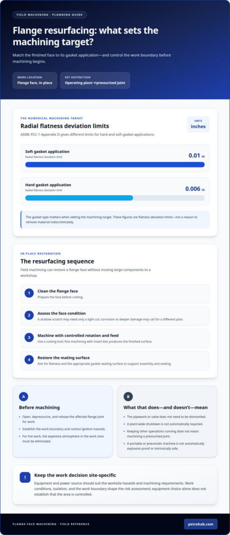
A plant-wide shutdown is not automatically required for flange-face machining. The affected flange joint must be opened, depressurized, and released for work, but the pipework or valve does not need to be dismantled. That distinction is central to eliminating catastrophic explosion anxiety during live flange face machining: establish the work boundary and control ignition hazards before machining begins.
Concern about an explosion is justified in hazardous industrial environments. For hot work, the explosive atmosphere in the work area must be eliminated, according to the U.S. Environmental Protection Agency. Keeping the wider plant operating does not mean machining a pressurized joint or overlooking site conditions.
This article explains when affected equipment must be taken out of service, how field machining can restore a flange face, and how resurfacing can support leak prevention. It also shows how on-site machining fits into maintenance planning, helping safety managers and engineers distinguish localized work isolation from a plant-wide shutdown.
Key Takeaways
- Understand how flange-face condition affects the mating surface and the joint’s ability to seal after assembly.
- See how onsite resurfacing can address damaged flange faces without moving large equipment to a workshop.
- Learn which machining and surface-finish considerations matter when restoring a flange for its gasket application.
- Recognize why controlling ignition hazards in the work area is essential when planning hot work in an operating facility.
Flange facing during plant maintenance and shutdowns
Flange facing restores a flange’s flatness and smoothness so the assembled faces can form a sealing surface. For maintenance planning, the key distinction is between keeping the plant operating and machining a joint that remains pressurized.
Industrial Flange Facing Applications
Flange facing machines a flange surface to restore it for assembly and sealing. It is used in oil and gas, petrochemical, chemical, and power-generation facilities, where flange joints connect process equipment and piping. A corroded or uneven face can compromise alignment during assembly. Resurfacing can address flange damage during maintenance and support leak prevention without moving large components to a workshop.
Selecting Equipment for Live Machining
Choose a flange-facing machine and power source to suit the worksite hazards and machining requirements. Pneumatic machines are commonly used in oil and gas, and both hydraulic and pneumatic drives are options for flange facing. However, a pneumatic or portable machine is not automatically explosion-proof or intrinsically safe. The explosive atmosphere in a hot-work area must be eliminated, according to the U.S. Environmental Protection Agency; equipment choice alone does not establish that condition.
Comparing Live Work with Flange Removal
This comparison distinguishes an operating plant from a flange joint that remains under pressure. The affected joint must be opened, depressurized, and released for machining; the pipework or valve does not need to be dismantled. Removing the flange adds disassembly and handling, while field machining can avoid moving the component. Keeping other plant operations running does not mean machining a pressurized joint. Isolation and the work boundary shape the risk assessment.
Responding to Alarms, Leaks, and Ignition
Emergency response means stopping exposure and following the facility’s alarm and evacuation procedures. If a gas alarm sounds, stop machining when it is safe to do so, alert site control, and withdraw by the designated route. In the event of a leak or ignition, raise the alarm, keep personnel clear, and let designated responders manage the incident. Restart only after responsible site personnel authorize work and the hazard is controlled.
Field machining during plant shutdowns
Field machining during a shutdown lets crews address damaged flange faces while equipment is accessible for planned maintenance. Lockout/tagout, process conditions, and the work permit determine whether machining can proceed.
Shutdown Controls and Lockout
Lockout/tagout controls hazardous energy before mechanical work begins. A shutdown alone does not prove equipment is isolated. Crews identify energy sources, follow the site’s isolation procedure, and verify the work boundary before machining. This is particularly important around exchangers, valves, and connected piping, where pressure or an unexpected release could expose workers. Once isolation is verified, flange work can focus on corrosion, face condition, and the required finish.
Gas Testing and Continuous Monitoring
Gas testing and monitoring assess whether flammable gas is present near the machining location. Alarm thresholds and test frequency must follow the facility’s permit and hazard assessment; there is no universal numerical threshold for every process and instrument. A potential release, changing ventilation, or nearby hydrocarbon work can affect readings. Because combustible gas combined with an ignition source can cause a fire or explosion, readings must inform the decision to proceed.
Permit Decisions for Live Machining
A permit-to-work decision determines whether the proposed task and conditions allow machining to proceed. Postpone or prohibit work if isolation cannot be verified, gas readings exceed site limits, alarms occur, or the work area cannot be controlled. Assess hazardous-area classification against the site’s documented process hazards and equipment requirements. ASME PCC-1 provides guidance for pressure-boundary bolted flange-joint assembly; it doesn’t itself authorize machining on pressurized piping.
Barriers, Exclusion Zones, and Evacuation
Barriers and exclusion zones control access around the flange and keep escape routes clear. Set boundaries according to the site’s hazard assessment, equipment layout, potential gas release, and emergency plan. Use that plan to determine evacuation distances rather than assuming a universal radius. If an alarm, leak, or ignition occurs, stop work when safe, alert site control, and withdraw by the designated route. Key hazards include mechanical damage, ignition sources, and released hydrocarbons.
On-site flange resurfacing
On-site flange resurfacing machines a flange face in place to create a new mating surface for assembly. It suits large pipelines and fixed equipment that would be difficult to move to a workshop. The machine can be mounted at different angles, including inverted, to accommodate the flange position. This is useful at locations such as heat exchangers, where limited clearance can complicate removal and transport.
The machining process begins by cleaning the flange face, then uses a cutting tool with controlled rotation and feed. Fine machining with insert bits produces the finished surface. The aim is to restore flatness and provide the appropriate gasket seating surface, not to remove material indiscriminately. A shallow scratch may need only a light cut, while corrosion or deeper damage may call for a different plan based on the face condition.
Surface finish and flatness affect how the assembled joint seats. ASME PCC-1 Appendix D gives radial flatness deviation limits of 0.006 inches for hard gasket applications and 0.01 inches for soft gasket applications. These values illustrate why gasket type matters when setting the machining target. For an RTJ connection, restoring the ring groove’s geometry and surface condition is also critical to the seal. Field machining can repair existing grooves or cut new ones when required by the joint design.
On-site machining can restore flange faces of different diameters, including large pipeline connections. The final check must confirm that the machined face suits the intended gasket and assembly requirements. Resurfacing supports flange integrity by preparing the mating surfaces, but it does not replace correct gasket selection, alignment, or controlled joint assembly.
Onsite flange face machining and leak prevention
Leak prevention depends on more than machining a flange face. The surfaces must suit the gasket, meet the joint’s finish requirements, and be assembled with controlled alignment and bolt loading. A maintenance plan should connect machining acceptance criteria with operating conditions and approved work controls. This coordination supports efforts to eliminate catastrophic explosion anxiety during live flange face machining without treating resurfacing as a substitute for hazard control.
Field machining can remove damage and restore a sealing surface without transporting fixed equipment. For ASME B16.5 raised-face flanges, the typical surface finish range is 125 to 250 microinches Ra. The target finish must match the gasket and joint design. A polished-looking face alone doesn’t prove suitability; the machining result must deliver the required surface texture and geometry.
Flatness matters because uneven contact can concentrate gasket loading instead of distributing it across the seating area. Machining may restore a spiral-grooved finish, while a ring-type-joint connection may need its groove repaired or recut. RTJ groove sidewalls must have a surface finish no greater than Ra 1.6 µm. The appropriate target depends on the connection and gasket type, not appearance alone.
After cutting, assembly remains critical. ASME PCC-1 covers pressure-boundary bolted flange-joint assembly, including surface preparation, gasket selection, bolt lubrication, torque application, and controlled tightening sequences. These steps work together: a correctly machined face can still leak if the gasket is unsuitable or bolt loading is uneven. For teams focused on eliminating catastrophic explosion anxiety during live flange face machining, link the machining plan to the site’s ignition controls and clear stop-work criteria.
For an exchanger connection, match machining acceptance criteria to its gasket and joint design, then preserve those criteria during assembly. Onsite resurfacing supports leak prevention by restoring mating surfaces, but it cannot replace appropriate joint assembly. For hot-work containment planning, discuss hot-work enclosure options as part of the site’s hazard controls.
PetroHab
PetroHab LLC provides purpose-built Hot Work Safety Enclosures (HWSE) and shutdown systems for hot work in hazardous industrial environments. For planning around flange maintenance, PetroHab LLC’s pressurized welding enclosures and Quadra-Lock Panels help establish a controlled hot-work setup. The Safe-Stop Automatic Shutdown System monitors gas levels and pressure to support worker safety as conditions change. These systems complement, rather than replace, the isolation, permit, and machining decisions required for the flange joint. Choose a configuration based on the work scope and site hazards, with personnel protection and ignition control central to the plan. Contact PetroHab LLC to discuss hot-work safety equipment for your facility.
Plan the next maintenance window with control
Make the service decision part of the work scope, not an assumption made at the flange. Before scheduling, align operations, maintenance, and safety teams on the joint’s condition, isolation boundary, hot-work controls, and stop-work criteria. This turns concern about eliminating catastrophic explosion anxiety during live flange face machining into a defined engineering decision grounded in site conditions and approved work controls.
Keep the decision specific to the equipment and task. If the affected joint cannot be isolated and released, or the work area cannot meet the site’s hot-work controls, do not treat machining as routine maintenance. Resolve those conditions before setting the work plan. For facilities assessing containment and ignition-control equipment alongside their maintenance planning, discuss your site’s requirements with PetroHab.
A deliberate review gives the team a clearer basis for selecting the work window and protecting personnel. Put hazard control ahead of schedule pressure.
Frequently Asked Questions
Does the plant have to be taken out of service?
No, the entire plant does not automatically need to stop. The affected flange joint must be opened, depressurized, and released before machining; keeping surrounding units operating does not make that joint ready for work. Base the operating decision on the isolation boundary, nearby process interactions, and approved permit. For example, an exchanger train may remain in service only if the connection and worksite meet facility controls.
When should in-situ machining be applied?
Use in-situ machining when a flange can be restored in place and moving connected equipment would complicate maintenance. A fixed pipeline flange or exchanger connection can be assessed for access, face damage, gasket type, and required finish. If inspection finds damage beyond what machining can address, or the face cannot meet restoration requirements, reassess the repair scope before proceeding.
What hot-work controls, fire watch, and emergency shutdown procedures are needed?
Set hot-work controls through the facility’s permit and emergency plan, rather than assuming the machining method controls every hazard. The plan should assign responsibility for atmospheric testing and monitoring, fire watch, alarm communication, shutdown authority, and evacuation routes. If readings reach site limits, or a leak or ignition occurs, stop work when safe, raise the alarm, and follow site response and shutdown procedures.
What explosion-proof or intrinsically safe tools and equipment are suitable for live flange machining?
Pneumatic and hydraulic drives are both options, but a pneumatic or portable machine is not automatically explosion-proof or intrinsically safe. The explosive atmosphere in the hot-work area must be eliminated, and the equipment must suit the worksite hazards and machining requirements.
How do operators assess hazardous-area classification before live flange machining?
Assess the hazardous-area classification against documented process hazards and equipment requirements. The permit decision should also consider the facility’s hazard assessment, gas readings, and whether conditions in the work area can be controlled.