
Blog Posts
Fire-Resistant Air Ducting: Ensuring Integrity in Pressurized Safety Enclosures
In a pressurized hot work enclosure, the ducting isn’t a secondary component. It’s the lifeline. When fire-resistant air ducting fails, the entire atmosphere inside a Hot Work Safety Enclosure (HWSE) is compromised, and every person working within it faces immediate, uncontrolled exposure to hydrocarbon ingress. That’s not a risk scenario. That’s a catastrophic breakdown of the primary safety barrier.
Safety managers and engineers working in offshore and onshore heavy industry already understand the stakes. Maintaining positive pressure inside a pressurized habitat demands components that perform without exception, in corrosive environments, under continuous thermal and mechanical stress, and in full compliance with ATEX and NFPA standards. Any weak point in the ducting system creates a direct path for hazardous gases to enter the work area.
This article addresses the core question every operations team should be asking: what specifications does air ducting need to meet to maintain structural integrity and fire resistance inside a pressurized welding enclosure? You’ll learn how ducting selection directly impacts atmosphere control, regulatory compliance, and operational uptime, and how it functions as a critical part of a total HWSE safety solution.
Key Takeaways
- Fire-resistant air ducting is not a peripheral component — it is a primary safety barrier that directly determines whether a pressurized Hot Work Safety Enclosure can maintain a controlled, hazard-free atmosphere.
- Specific certifications, including NFPA 701 flame propagation ratings and UL 94 V-0 classifications, define the minimum material performance thresholds that industrial ducting must meet to be considered compliant in hazardous zone applications.
- Even minor pressure losses caused by duct leaks, frayed seams, or failed connections can compromise the positive pressure differential that keeps flammable gases out of the enclosure — understanding the physics of this failure mode is critical for operations teams.
- Proper installation and pre-operational inspection protocols, particularly in high-wind offshore environments, are as important as material specification when it comes to sustaining ducting integrity over the life of a deployment.
- PetroHab’s air ducting is engineered to integrate directly with its patented Quadra-Lock panel system and Safe-Stop Automatic Shutdown System, delivering a unified HWSE solution where every component is designed to perform as part of a single, interdependent safety architecture.
The Role of Fire-Resistant Air Ducting in Hazardous Zones
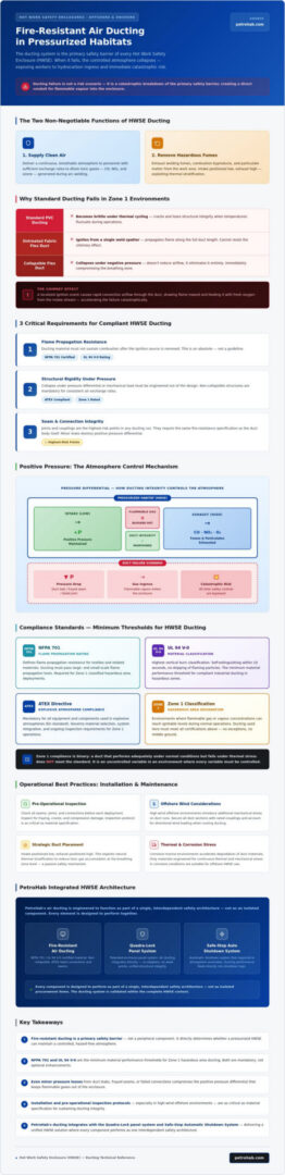
Inside a Hot Work Safety Enclosure, air ducting performs two simultaneous and non-negotiable functions: delivering a continuous supply of clean, breathable air to personnel and removing welding fumes, combustion byproducts, and particulate matter from the work area. It’s the respiratory system of the entire enclosure. When that system is built from substandard materials, the consequences aren’t gradual. They’re immediate and potentially fatal.
Fire-resistant air ducting, in the context of an HWSE, refers specifically to ducting constructed from materials that resist ignition, suppress flame propagation, and maintain structural integrity under thermal stress. This is a fundamentally different specification from standard HVAC ducting. In Zone 1 classified environments, where flammable gas or vapour concentrations can reach ignitable levels during normal operations, the ducting material itself becomes a potential ignition pathway if it’s not rated for the hazard.
Standard PVC ducting and untreated fabric flex duct present a catastrophic risk in these environments. PVC becomes brittle and cracks under thermal cycling. Untreated fabric can ignite from a single errant weld spatter and propagate flame along its entire length. Neither material can prevent what’s known as the chimney effect: a localized ignition event that causes rapid convective airflow through the duct, drawing the flame inward and feeding it with fresh oxygen from the intake stream.
Maintaining the Breathable Atmosphere
Safe welding operations require consistent air exchange rates sufficient to dilute and exhaust toxic gases including carbon monoxide, nitrogen dioxide, and ozone generated during arc welding processes. Achieving those exchange rates depends entirely on non-collapsible ducting structures. A flexible duct that collapses under negative pressure doesn’t just reduce airflow; it eliminates it. Strategic duct placement, with intake positioned low and exhaust positioned high to exploit natural thermal stratification, further reduces the risk of toxic gas accumulation at the breathing zone level.
Ducting as a Barrier to Ignition
The relationship between ducting integrity and the overall fire rating of a pressurized habitat is direct. Fire-resistant air ducting prevents external sparks and burning debris from entering the air stream and being carried into the enclosure interior. It also contains any localized ignition event at the duct wall rather than allowing it to propagate. The specific hazard of hydrocarbon ingress through a compromised air line is particularly acute: a duct failure near a process area can create a direct conduit for flammable vapour into the enclosure, bypassing every other safety control in place.
- Flame propagation resistance: Ducting material must not sustain combustion after an ignition source is removed.
- Structural rigidity: Collapse under pressure differential or mechanical load must be engineered out of the design, not managed through field workarounds.
- Seam and connection integrity: Joints and couplings are the highest-risk points in any ducting run; they require the same fire-resistance specification as the duct body itself.
In Zone 1 environments, there’s no acceptable middle ground between compliant and non-compliant. A duct that performs adequately under normal conditions but fails under thermal stress doesn’t meet the standard. It represents an uncontrolled variable in an environment where every variable must be controlled.
Technical Standards and Material Specifications for Industrial Ducting
Selecting ducting for a pressurized welding enclosure isn’t a procurement decision. It’s an engineering decision with direct safety consequences. The material specification determines whether the duct contains a thermal event or accelerates it, whether it maintains airflow integrity under mechanical stress or collapses, and whether it meets the regulatory threshold for Zone 1 classified environments or simply approximates it.
Two certification frameworks define the minimum acceptable performance for fire-resistant air ducting in industrial applications. NFPA 701 establishes standardized test methods for flame propagation in flexible fabric and film materials. A material that passes NFPA 701 testing has demonstrated it will not sustain combustion after an ignition source is removed, and that flame spread along the duct surface remains below the threshold that would allow a localized event to become a system-wide failure. UL 94 V-0 classification applies specifically to polymer and plastic components within the ducting assembly, including end collars, coupling rings, and any rigid transition pieces. V-0 is the most stringent UL 94 rating: the material must self-extinguish within ten seconds of flame removal, with no dripping of burning particles.
Anti-static properties are a separate but equally non-negotiable requirement. In ATEX-classified environments, an ungrounded duct carrying high-velocity airflow can accumulate electrostatic charge sufficient to generate a spark discharge. That discharge, in a Zone 1 atmosphere, is an ignition source. Compliant ducting must incorporate conductive threads or carbon-loaded coatings that dissipate static charge continuously, preventing accumulation at any point along the duct run.
Material selection comes down to application conditions. PVC-coated polyester ducting offers good chemical resistance and flexibility at moderate cost, making it appropriate for general industrial environments where temperature exposure remains within standard operating ranges. Silicone-coated fibreglass ducting operates at significantly higher continuous temperatures and provides superior thermal stability in applications near heat sources or in environments with elevated ambient temperatures. Neither material is universally superior; the operating environment dictates the specification.
Certifications for Offshore and Onshore Use
Offshore deployments introduce certification requirements that onshore applications may not trigger. UV degradation is a genuine structural threat on open-deck platforms where ducting is exposed to direct solar radiation for extended periods. Polymer coatings that aren’t UV-stabilised become brittle, crack along seam lines, and lose their flame-retardant properties as the base material degrades. Chemical resistance is equally critical in refinery environments, where ducting surfaces may be exposed to hydrocarbon vapours, cleaning solvents, and acidic condensates. The duct coating must resist chemical attack without releasing toxic off-gases that would re-contaminate the air supply it’s delivering.
Mechanical Integrity and Reinforcement
Structural integrity under pressure differential is achieved through spring steel wire helix reinforcement embedded within the duct wall. This helical structure prevents collapse under negative pressure conditions and maintains the circular cross-section that sustains designed airflow rates. Without it, a flexible duct under suction load will deform, restrict airflow, and eventually fail at the weakest point in the run. On active industrial sites, scuff strips along the duct exterior provide abrasion resistance where ducting crosses walkways or contacts structural steelwork, preventing surface wear from compromising the fire-retardant coating beneath.
Understanding how these specifications interact across a complete ducting run is essential for operations teams specifying components for a new HWSE deployment. Explore PetroHab’s HWSE ducting specifications to see how material selection, reinforcement design, and certification compliance are integrated into a single, field-ready solution.
Maintaining Positive Pressure: The Intersection of Ducting and HWSE
Positive pressure is the mechanism that keeps a pressurized habitat safe. By maintaining an internal pressure slightly above the surrounding atmosphere, the enclosure creates a continuous outward airflow at every potential ingress point, physically preventing flammable gases from migrating inward. The ducting system is what generates and sustains that differential. If the ducting fails, the pressure fails. If the pressure fails, the exclusion barrier fails. The sequence is that direct.
Calculating the airflow required to maintain positive pressure isn’t guesswork. It’s a function of duct diameter, duct length, the number of bends in the run, and the target pressure differential across the enclosure envelope. Friction loss accumulates with every metre of duct length and every directional change. A blower rated for a specific CFM output at zero static pressure will deliver significantly less airflow at the end of a long, complex duct run. Operations teams must account for that loss when specifying blower capacity, or the system will be chronically under-pressurized from the first day of deployment.
Leaks at duct connections and seams are the most common source of unplanned pressure loss. A poorly clamped coupling or a frayed seam under tension doesn’t just reduce delivered airflow; it creates a low-pressure zone at the leak point that can draw in surrounding atmosphere. In a Zone 1 environment, that surrounding atmosphere may contain flammable vapour. The leak becomes an ingress pathway, and the ducting intended to protect personnel becomes the mechanism of their exposure. Fire-resistant air ducting with rated seam construction and mechanically secured couplings eliminates that failure mode at the component level.
Pressure Monitoring and Manometers
Manometers installed at the enclosure provide continuous, real-time visibility into the pressure differential between the interior and the external atmosphere. A drop in differential pressure that isn’t explained by a change in blower operation indicates a loss of ducting integrity somewhere in the run. That signal demands immediate investigation. In an integrated HWSE architecture, pressure monitoring connects directly to the Safe-Stop Automatic Shutdown System, which can trigger a controlled shutdown of hot work operations the moment pressure falls below the minimum safe threshold, removing the dependence on manual intervention during a time-critical event.
Optimizing Duct Layout for Maximum Pressure
Duct layout decisions made during installation have a direct and lasting impact on system performance. Every 90-degree bend introduces friction loss equivalent to several metres of straight duct run. Minimizing bends, maintaining the largest practical duct diameter for the blower specification, and routing duct runs along the shortest viable path all reduce friction loss and preserve delivered CFM. Coupling integrity at the point where ducting meets the Quadra-Lock panels is particularly critical; any air escape at that junction undermines the sealed enclosure geometry that the panel system is engineered to create. Secure, rated connections at every interface aren’t optional. They’re the baseline.
Operational Best Practices: Installation and Maintenance
Compliant materials and correct certifications establish the performance ceiling for fire-resistant air ducting. Field procedures determine whether that ceiling is ever actually reached. A duct constructed from NFPA 701-rated fabric and reinforced with spring steel helix will fail prematurely if it’s installed without pre-operational inspection, improperly anchored in high-wind conditions, or stored in ways that degrade the flame-retardant coating between deployments. The engineering only protects personnel if the operational discipline matches it.
Installation Procedures for Habitat Ventilation
Installation begins before a single clamp is tightened. Three sequential checks establish the baseline integrity of the entire air management system:
- Step 1: Inspect the air intake source. Confirm the intake is positioned away from process areas, drain points, and any location where hydrocarbon vapour concentrations could be drawn into the supply stream. An intake sited incorrectly contaminates the entire pressurized enclosure regardless of how well the ducting itself performs.
- Step 2: Secure all duct connections with heavy-duty industrial clamps. Every coupling point is a potential pressure loss site. Clamps must be torqued to the manufacturer’s specification, not hand-tightened. Inspect each seam and collar for tears, pinholes, or fraying before the run is pressurized. In offshore environments, vibration from deck machinery can loosen connections over time; a secondary retention check after the first 24 hours of operation is standard practice.
- Step 3: Verify flow direction and check for internal obstructions. Confirm airflow moves from the blower toward the enclosure, not in reverse. Inspect the interior of each duct section for debris, collapsed sections, or manufacturing defects before the system goes live. An undetected obstruction reduces delivered CFM and creates a low-pressure zone that undermines the positive pressure differential the entire system is engineered to maintain.
Anchoring is a separate discipline in offshore deployments. High-wind environments on open-deck platforms generate lateral loads that unsecured ducting can’t resist. Duct runs must be anchored to fixed structural members at regular intervals using rated strapping, not improvised cable ties or rope. An unsecured duct that shifts under wind load stresses its coupling points and can separate from the enclosure panel interface, creating an immediate ingress pathway.
Routine Maintenance and Replacement Cycles
Thermal fatigue in fire-resistant fabrics presents as surface discolouration, stiffening of the duct wall, and micro-cracking along the helix wire contact points. These are not cosmetic issues. A fabric that has lost flexibility under thermal cycling has also degraded its flame-propagation resistance. Visual inspection alone is insufficient; tactile checks along the full duct length identify stiffened sections that visual inspection misses.
Replacement schedules must account for environmental exposure, not just elapsed time. A duct deployed on an open offshore deck in direct UV exposure and salt spray will reach end-of-service condition faster than an identical duct used in a sheltered onshore application. Inspection records documenting deployment duration, environmental conditions, and observed degradation indicators provide the evidence base for replacement decisions and satisfy the audit trail requirements of ATEX compliance documentation.
Certified technicians must oversee air management setup and sign off on pre-operational inspections. Delegating these checks to unqualified personnel removes the accountability structure that regulatory frameworks require and eliminates the technical judgment needed to identify marginal conditions before they become failures.
Storage between projects requires clean, dry conditions away from chemical exposure. Ducting stored in contact with solvents, fuels, or acidic compounds absorbs those materials into the coating, compromising flame-retardant properties before the next deployment begins. Each stored section should be tagged with its last inspection date and deployment history so that field teams can make informed decisions about serviceability without relying on visual assessment alone.
PetroHab Air Ducting: Engineered for Industrial Safety Excellence
Every component inside a Hot Work Safety Enclosure carries a defined function. PetroHab’s approach to air ducting rejects the idea that any single component can be treated in isolation. The ducting doesn’t just supply air; it completes the safety architecture. Specified, tested, and deployed as part of the broader HWSE ecosystem, it operates in direct coordination with the Quadra-Lock panel system and the Safe-Stop Automatic Shutdown System to deliver a unified, interdependent barrier against hazardous atmosphere ingress.
That integration matters operationally. When ducting, panels, and shutdown controls are engineered to work together, the failure modes of each component are accounted for in the design of the others. There are no compatibility assumptions, no field-fabricated adaptors, and no gaps in the safety envelope created by mismatched specifications.
The PetroHab Advantage
The sealing geometry of the Quadra-Lock panel system depends on duct connections that maintain rated integrity at the panel interface. PetroHab’s pressurized welding habitat technology is built around this synergy: fire-resistant air ducting specified to match the panel coupling dimensions, eliminating the pressure loss that mismatched components introduce at the most critical junction in the entire air management run.
Ducting is available in customizable lengths and diameters to suit specific project footprints, whether that’s a compact onshore repair enclosure or a large-diameter offshore habitat on an open-deck platform. Technical support and on-site training cover habitat air management setup, pre-operational inspection procedures, and the correct anchoring protocols for high-wind environments. That knowledge transfer doesn’t end at commissioning; it builds the operational competence that sustains ducting integrity across the full deployment lifecycle.
Elevating Site Safety Protocols
Unplanned operational downtime in hazardous zone hot work is rarely caused by a single catastrophic failure. It’s caused by marginal components that degrade incrementally until they cross a threshold. Reliable air management hardware eliminates that attrition. When the ducting holds pressure, the enclosure holds pressure, and hot work operations proceed without interruption.
PetroHab serves offshore and onshore facilities across multiple continents, with ducting available through both direct sales and leasing arrangements to support the variable operational tempo of multi-site project portfolios. Compliance with global hazardous environment standards isn’t a marketing position; it’s the engineering baseline every component is held to before it leaves the facility.
- Integrated ecosystem: Ducting specified to interface directly with Quadra-Lock panels and Safe-Stop controls.
- Flexible procurement: Leasing and direct sales options for multi-continent operations.
- Technical support: On-site training and air management consultation for each deployment.
If your operations require fire-resistant air ducting that performs as part of a total HWSE solution rather than as a standalone component, contact PetroHab for a specialized HWSE equipment consultation.
Build Your HWSE on Components That Won’t Compromise
The case is straightforward: fire-resistant air ducting isn’t a line item to optimize for cost. It’s the component that determines whether positive pressure holds, whether the atmosphere inside a pressurized enclosure stays controlled, and whether personnel are protected when conditions deteriorate. Get the specification wrong, and every other safety control in the system is working against a compromised foundation.
Three principles carry through everything covered here. Material certification isn’t negotiable in Zone 1 environments. Pressure integrity depends on the full ducting run, not just individual components. And field discipline during installation and maintenance is what converts compliant hardware into sustained protection.
PetroHab’s ducting is engineered to deliver on all three, backed by patented Quadra-Lock technology, compliance with international safety standards, and global technical support that extends through the full deployment lifecycle.
Your operations deserve a solution where every component is accountable. Request a quote for fire-resistant ducting and HWSE solutions from PetroHab today.
Frequently Asked Questions About Fire-Resistant Air Ducting
What is the difference between fire-resistant and fire-retardant air ducting?
Fire-resistant ducting is engineered to maintain structural integrity and limit flame spread under sustained thermal exposure, meeting specific performance thresholds defined by standards such as NFPA 701. Fire-retardant ducting has been chemically treated to slow ignition and reduce flame propagation, but that treatment can degrade over time through UV exposure, chemical contact, or thermal cycling. In Zone 1 classified environments, fire-resistant construction is the required specification, not a treated alternative.
Can fire-resistant ducting be used in ATEX Zone 1 environments?
Yes, provided it meets the full ATEX compliance requirements for the classified zone, which extend beyond flame resistance alone. Ducting used in Zone 1 must incorporate anti-static properties to prevent electrostatic charge accumulation, which represents an independent ignition risk in atmospheres where flammable vapour concentrations can reach ignitable levels during normal operations. Material certification, anti-static construction, and verified seam integrity are all mandatory, not optional, for Zone 1 deployment.
How often should industrial air ducting be inspected for safety compliance?
Inspection frequency should be determined by deployment conditions rather than a fixed calendar interval. Ducting on open offshore decks exposed to UV radiation, salt spray, and mechanical vibration degrades faster than ducting in sheltered onshore environments. A pre-operational inspection before every deployment is a non-negotiable baseline. After commissioning, a secondary check within the first 24 hours of operation catches connection loosening caused by vibration, and documented inspections at regular intervals throughout the deployment satisfy ATEX audit trail requirements.
Does the length of the ducting affect the positive pressure inside a welding habitat?
It does, directly. Every metre of duct length introduces friction loss that reduces the airflow delivered at the enclosure end of the run. Directional bends compound that loss further. A blower rated for a specific CFM output at zero static pressure will deliver measurably less airflow through a long, complex duct run, which means the positive pressure differential inside the habitat will be lower than the blower specification suggests. Blower capacity must be sized to compensate for the total friction loss of the actual installed duct run, not the theoretical output figure.
What materials provide the best fire resistance for air ducting in oil and gas applications?
Silicone-coated fibreglass ducting provides the highest thermal stability and is the preferred specification where continuous exposure to elevated temperatures or proximity to heat sources is a factor. PVC-coated polyester ducting offers strong chemical resistance and flexibility for general industrial applications where temperature exposure stays within standard operating ranges. The correct material isn’t universal; it’s determined by the specific thermal environment, chemical exposure profile, and whether the deployment is onshore or on an open offshore deck where UV degradation becomes an additional structural concern.
Is anti-static ducting mandatory for all pressurized habitats?
In any ATEX-classified environment, anti-static ducting isn’t a recommended upgrade; it’s a compliance requirement. High-velocity airflow through an ungrounded duct generates electrostatic charge that accumulates along the duct surface. In a Zone 1 atmosphere, a static discharge from that surface is a credible ignition source. Compliant fire-resistant air ducting must incorporate conductive threads or carbon-loaded coatings that continuously dissipate charge, eliminating accumulation at any point in the run. Habitats operating outside classified zones should still assess static risk based on the specific process environment.
How do I secure air ducting to a PetroHab Quadra-Lock panel?
Connections at the Quadra-Lock panel interface must be secured using heavy-duty industrial clamps torqued to the manufacturer’s specification, not hand-tightened. The coupling dimensions of PetroHab’s ducting are specified to match the Quadra-Lock panel interface directly, which eliminates the pressure loss that mismatched components introduce at that junction. In offshore environments, a secondary retention check after the first 24 hours of operation is standard practice, as deck vibration can loosen connections that were correctly torqued at installation. Any air escape at the panel interface undermines the sealed enclosure geometry the system is designed to create.
What happens to the air ducting if the Safe-Stop system triggers an emergency shutdown?
When the Safe-Stop Automatic Shutdown System detects a pressure drop below the minimum safe threshold, it initiates a controlled shutdown of hot work operations. The ducting itself remains physically intact through that event; the shutdown removes the ignition risk rather than altering the duct structure. Because PetroHab’s ducting is specified to integrate directly with the Safe-Stop system and Quadra-Lock panels as a unified architecture, the failure modes of each component are accounted for in the design of the others. Post-shutdown, the ducting run must be inspected to identify the pressure loss event that triggered the shutdown before operations resume.