
Blog Posts
Interlocking Habitat Panels for Industrial Facilities
Interlocking habitat panels are not generally trimmed to change their module width. They may be cut to length, but walls are assembled from whole modules, so the fixed width affects the layout and fit.
A precise fit matters in industrial facilities, where panel joints, attachments, and wall configuration contribute to enclosure performance. Understanding how a system is assembled helps you identify where adjustments are possible and where the design must accommodate panel dimensions.
This article explains how panels attach, what their construction can conceal, and how interlocking affects structural performance. You’ll also learn how to approach trimming and layout decisions before they affect installation or enclosure integrity.
Key Takeaways
- Plan around the panels’ fixed module width; cutting to length doesn’t change how wide each panel is.
- Understand how base, top, and side profiles, clips, and gaskets work together to secure panel joints.
- Look beyond the panel face to understand how the construction handles concealed fastening and connected joints.
- Assess structural performance as a system, considering panel connections and wall configuration rather than interlocking alone.
Can the wall panels be trimmed to width?
For modular building units, interlocking habitat panels can be cut to length, but not across their width. Walls use whole modules, so each panel’s fixed width determines the layout.
This distinction matters at corners, doorways, and equipment clearances. If a wall run ends between module edges, resolve the difference through the layout, not by narrowing a panel. Measure wall runs and openings before arranging the modules. Plan for any remaining width at an end or return that can accommodate it.
Cutting a panel to length adjusts its height or run dimension. Preserving its module width keeps the interlocking edges aligned. Treat these as separate measurements in the layout. Record the required cut length and full module width for each wall position; changing one dimension does not change the other.
Prefabricated geopolymer panels are designed for handling by two people. That handling consideration supports modular assembly: plan how each full-width panel will be carried into position, aligned with its neighbor, and joined. Restricted access or nearby equipment can affect the sequence, so map the installation path before placing modules.
Wall panels and modular roof systems are separate assemblies. A fixed wall-panel width does not establish the module width or trimming allowance for a roof. Treat the roof as its own system, with its own dimensions and connections, rather than assuming wall-panel cuts or joints apply overhead.
Permit requirements depend on the jurisdiction and facility context. Relevant factors include building use, whether installation changes the structure, and the site’s hot-work controls. Before assembly, document wall dimensions, openings, panel orientation, and planned cut lengths. Use the layout to coordinate the work with the facility’s applicable approval process.
Interlocking walls are built from whole modules because panels cannot be trimmed to width. Account for that fixed width when planning each run, rather than treating it as an adjustable dimension. If the planned wall extent does not align with the module arrangement, resolve the difference in the layout and at an appropriate end condition while retaining whole panels. This keeps the wall plan consistent with the panels’ interlocking construction.
Installation sequence and attachment
Panel installation progresses from the base support to the upper and side profiles. Each interface matters because it determines how panels align and connect across the enclosure.
Installation Sequence
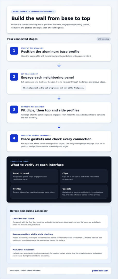
Begin by positioning the aluminum base profile along the planned wall line. Set panels into the base and join neighboring units through their tongue-and-groove edges. Add clips, then fit the top and side profiles to complete the wall assembly. Place gaskets where panels meet profiles.
- Align the aluminum base profile with the intended wall layout.
- Set each panel into the base and engage the tongue-and-groove joint with its neighbor.
- Fit clips, then install the top and side profiles.
- Place gaskets at panel-to-profile joints and inspect each connection.
Before assembly, compare the wall layout with the floor line, openings, and adjoining surfaces. A doorway, for example, interrupts the panel run, affecting where full modules and joints land. Check alignment as the wall progresses, not just at the final panel.
Panel Attachment
The attachment system combines interlocking panel edges with clips and perimeter profiles. Tongue-and-groove joints connect adjacent panels, while clips and profiles complete the assembly. Gaskets sit at panel-to-profile joints, closing the interface between those components.
Inspect each connection as you assemble it. Confirm that neighboring edges engage, clips are in position, and profiles meet the intended panel edges. Check gasket placement at the base, top, and sides wherever panels contact profiles. These checks can reveal a misaligned joint before later panels restrict access.
For modular enclosure planning, review industrial habitat panel solutions alongside the wall layout. The attachment sequence gives installers a clear order of work, while the completed interfaces determine how the assembled panels meet the surrounding profiles.
Together, these components form the wall’s attachment arrangement: interlocking panel edges meet at tongue-and-groove joints, clips and top and side profiles complete the assembly, and gaskets sit at panel-to-profile joints.
Panel construction and concealed fastening
A panel’s visible face does not reveal every part of its construction. Interlocking edges connect neighboring units, while profiles and fastening components form interfaces that may be less visible after assembly. A finished wall can look continuous even though separate panels meet behind the surface.
Concealed fastening affects how the assembly should be inspected. A clean exterior seam alone cannot show whether a hidden connection is seated correctly. During installation, examine each accessible panel edge and connection before another component covers it. Note any joint that needs attention while its fastening remains visible.
Construction materials also affect handling. Prefabricated geopolymer panels are designed to be handled by two people. Their material and preformed edges are part of the unit, so crews should protect those edges during movement and positioning. A chipped or obstructed edge can interfere with the intended fit between adjoining panels.
Assess the panel and its connection separately. Check the face for damage, then inspect the edge profile, joining surfaces, and any exposed attachment points. Where a profile hides fastening hardware, complete the connection checks before fitting the cover. This sequence preserves visual access to the areas that need inspection.
For industrial buildings, an inspection plan should identify which joints remain visible and which become concealed. Mark panel locations on an assembly drawing, then note the connection points to inspect before covering them. This gives maintenance teams a reference when a later repair involves one wall section rather than the full enclosure.
Do not infer a panel’s full internal construction from its exterior appearance. Review the assembly details for the specific panel system, including its materials, edge geometry, and fastening interfaces. This helps engineers distinguish the panel body from the components that connect it to adjacent panels and surrounding profiles.
Structural performance of interlocked panels
Durability, maintenance, and environmental risks depend on panel materials, joint condition, and operating exposure. Inspect interlocked joints for movement or damage, and assess whether moisture, temperature changes, or site chemicals affect the enclosure materials.
A published test of 3D-printed geopolymer panels reported an ultimate compressive strength of 7.9 MPa. Mechanical testing took place 14 days after fabrication. That result describes tested panels under a particular test condition. It does not establish the load capacity of every assembled wall or habitat panel system.
Interlocking edges connect adjacent panels, so structural behavior depends on the assembled configuration, not just panel material strength. Wall height, support conditions, openings, and connection details all influence how forces pass through the assembly. A doorway, for example, interrupts a continuous panel run and changes the arrangement around the opening.
Use material test data as one input in engineering review. Then examine design details for the intended wall, including panel supports and joint connections. A compression result alone cannot demonstrate performance under every load direction, impact, or operating condition. Distinguish material strength from the capacity of the complete enclosure.
Focus maintenance on observable changes to panel faces, edges, and connected joints. Record damage or movement by location, then compare findings during later inspections. At sites with moisture or chemical exposure, include those conditions in the inspection plan because they can affect materials and interfaces over time.
For an industrial installation, document the wall configuration, support points, openings, and inspection findings together. This creates a practical basis for evaluating structural performance and maintenance needs. Review habitat panel system details when assessing panel construction for a hot-work enclosure.
PetroHab: PetroHab Hot Work Safety Enclosure (HWSE)
The Petro-Habitat™ Hot Work Safety Enclosure (HWSE) provides a modular, pressurized enclosure for hot work in hazardous industrial environments. It is designed for sites that need a dedicated habitat rather than a general building wall system.
PetroHab’s offering includes Quadra-Lock Panels, pressurized welding enclosures, and the Safe-Stop Automatic Shutdown System. Safe-Stop monitors gas levels and pressure, supporting worker safety during hot work. Select the enclosure configuration based on the work area and the protection needs identified for your operation.
For safety managers and engineers assessing panel design, the key decision is how the habitat’s enclosure and monitoring components fit the work plan. Contact PetroHab to discuss your hot-work enclosure requirements.
Turn panel planning into a project brief
Use your panel assessment to define the enclosure’s operating requirements. A useful project brief connects the work location, planned hot-work activities, access constraints, and facility safety procedures. Include a wall layout and identify openings or interfaces that could affect the enclosure’s fit. This gives the design discussion a clear operational starting point.
For interlocking habitat panels, the next decision is how the enclosure configuration supports the work plan, not simply whether individual panels fit. Identify the conditions the system must address, who will use the space, and how the installation will be reviewed and maintained. Clear project criteria help align the enclosure design with site operations.
PetroHab’s hot-work enclosure offerings provide a relevant path for industrial teams planning a dedicated habitat. Contact PetroHab about habitat panels to discuss your project requirements and move the planning forward with confidence.
Frequently Asked Questions
How are interlocking walls installed?
Plan the work area and component staging before habitat assembly begins. PetroHab provides training and certification programs for habitat assembly, disassembly, and maintenance. Use that training to prepare the crew for handling and inspection tasks. Coordinate setup with the site’s hot-work plan so equipment access and monitoring requirements are considered alongside the physical assembly.
What materials and designs are used for interlocking habitat panels?
PetroHab habitat panels use U.S.-made, premium silver-gray silicone-coated fiberglass cloth. Panel material specifications can vary, so confirm the requirements for the habitat configuration before selection. Design options vary by habitat: Petro-Habitat panels include interchangeable, window, intrusion, and protrusion panels. These configurations help teams account for viewing needs and equipment interfaces when planning an enclosure.
What sizes and specifications are available for interlocking habitat panels?
Panel dimensions depend on the habitat configuration. Petro-Shield is a mobile modular enclosure that expands in 4-foot increments, while Petro-Lite has a simple modular design. For specification planning, define the available work footprint, access points, and required enclosure arrangement. These inputs help determine which configuration fits the facility layout without assuming one panel size suits every installation.
How are habitat panels installed and assembled?
Plan enclosure assembly and safety monitoring as coordinated work packages. PetroHab’s automatic shutdown systems monitor differential pressure and gas levels, and are ATEX- and IECEx-certified (IEC 60079-13). Account for monitoring equipment in the setup plan so sensors and pressure monitoring align with enclosure operation. Optional oxygen and/or carbon-dioxide detectors are available for the automatic shutdown system.